Beomaster 3000-2 Type 2402 15V Power Supply Not Activating

38 replies
Hi All - This is a cross-post from AudioKarma (thread here) but I am hoping folks here may have more experience with this ... Basically, in my 3000-2, the 15V power supply is not activating unless I touch TR17B or TR17C with something metal. Once I do that and it switches on, the 15V power supply works great and I can listen to music (via Tape input) no problem. The unit has all new electrolytic capacitors including the main PS cap and both output caps, and new rectifiers.  I've confirmed every single component in the 15V PS circuit is operational.  I've also de-oxited all the pots that are fed by the 15V PS. Through a DBT, the below in yellow are the values before it starts conducting, but after I touch TR17B or TR17C and switches on, then the green values appear and all is good. 
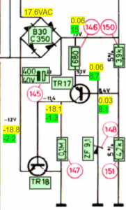
Any ideas as to why TR17 doesn't start conducting on its own when the unit is powered on? Scratching my head over here.  Appreciate any tips, suggestions, follow-up questions ... thank you!
Replace ZF9,1V........see if that helps, if not then at least you can eliminate it from the problem Craig
Craig: Thank you! I should have noted the work done ... everything in green boxes in my graphic (aka, every component in the circuit) has been replaced and/or tested OK. I see the same behavior either with the original 9.1V zener or with a new replacement 9.1V zener (specifically, a NZX9V1D). The issue (I think) is that for some reason there's no current through R150 & R151 to create the voltage drop needed at TR17's base, which once activated would flow current through R146 to activate ZD148. Despite weeks of scratching my head and trying different things, I can't determine why that's the case ... One idea was that the 15V PS load is too small - I confirmed in LTSpice that if the load is 1ohm, the PS won't engage.   (I'd post the LTSpice images, but I'm new to the forum and it won't let me either copy / paste images, upload them in the image upload tool, or attach them as files for some reason?  Is the image tool operational on this forum?)
Attachments (1)
1762310175297.png
Have you checked for broken traces and dry joints…..it’s got to be something obscure ?
Yeah, I've been checking it over for longer than I care to admit. Originally, I found quite a few, notably including TR18. Everything has been re-flowed and/or checked ... no harm in checking again I suppose! Thanks for the input ... looking forward to finding the issue and shaking my head, looking back on my troubleshooting, whatever it ends up being ...
if you disconnect all users from the 15v power supply rail and measure the output is the problem still present? Craig
Also bear in mind that some components can measure up fine when tested, but fail under load.....I've had this issue in the past, and replacement parts from suspect suppliers should be avoided...early transistors can still be found as old stock and are a safer bet than ebay Craig  
Great idea ... I had disconnected the pre-amp, but I had not disconnected it from the FM circuitry!  So I lifted various leads of all components getting fed by the + side trace of C145. With the +15v PS completely isolated ... it turns on correctly MOST of the time. When it gets stuck, now it's stuck at around +1.8V instead of the +0.06V I was seeing before ... when this happens if I touch anything in the circuit with my DMM lead, it switches on fully.  (This obviously implicates TR17 which SHOULD activate with that much voltage at its base ...) Once it does switch on to the full +15V, I can turn it off and on again repeatedly and it always activates correctly. I let it sit off overnight, and tried it this morning: it immediately went to the full +15V (I was wondering if maybe discharged capacitors had something to do with it ... apparently not). So from here, two things: 1 - why won't it turn on 1-5% of the time; 2 - what's shorting out in the FM circuit? Onwards!
Sounds like some progress.....change TR17 out and you should be good to go for the FM issue, dillen from the site always advocates the "half it" approach which is to go half way into the circuit and disconnect/test then work back or forth from that position.....always works for me ;¬) Craig
Wish it were that easy - turns out, when the PS isn't activating, TR17 is only seeing ~0.4V B to E. The attached image shows my Mastech is on the +PS, and my Fluke is on TR17 B to E.
Here's where things get weirder ... when I turn the unit OFF, TR17E-B BRIEFLY hits 0.6V+ and activates!  So while the unit turns off, the 15V PS turns ON for a moment before then going dead.
I managed to snap a pic when this happens.
Attachments (2)
PXL_20251111_013618402.jpg
PXL_20251110_025626532.jpg
Post a Reply
Attach Files
Max 10MB per file. Images, videos, PDFs, documents, archives, and 3D models accepted.
Please Log In to Reply

You must be logged in as a BeoWorld member to post replies to forum threads.

Rejoining the server...

Rejoin failed... trying again in seconds.

Failed to rejoin.
Please retry or reload the page.

The session has been paused by the server.

Failed to resume the session.
Please retry or reload the page.